From AI Render to AutoCAD: Elevations and True DXF Export
The least glamorous, most loved feature we ship: turn a render or photo into elevation drawings and export real vector files — DXF for AutoCAD, SVG for Illustrator, PDF for the set. Here is how it works and where traced linework honestly fits.
Every AI rendering tool can make a pretty picture. The question that decides whether a tool belongs in a *practice* — rather than a portfolio — is what happens when the pretty picture has to become drawings.
This post is about our answer: the elevations workflow and true vector export. It is the least glamorous feature we ship and, by usage among professional accounts, one of the most loved.
What it does
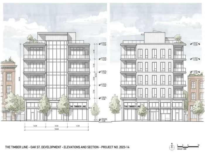
Give the platform a perspective render, a massing screenshot, or even a straight-on photo of an existing building. The elevations workflow generates clean architectural elevation drawings from it — and can produce a complete four-elevation sheet (front, rear, left, right) in a single pass.
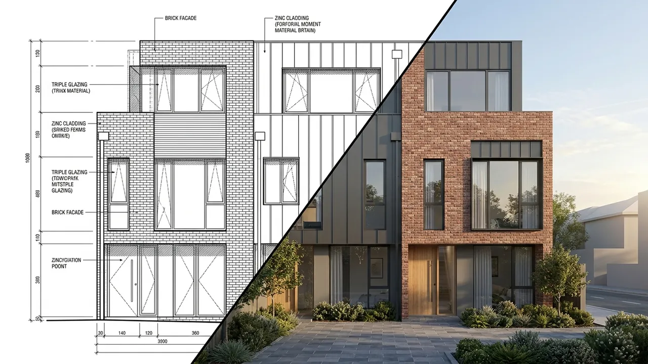
Then the part that matters: export is not a screenshot of lines. We trace the linework into real vectors:
- DXF — opens in AutoCAD as editable geometry. Layers of actual lines, not an image reference.
- SVG — for Illustrator and the graphics pipeline; scale it forever, restyle it freely.
- PDF — for the issue set, the deck, the consultant email.
That distinction — real vectors versus a picture of a drawing — is the whole feature. A raster elevation is a dead end; you can look at it. A DXF is a starting point; you can *work* on it.
The two directions people use it
Forward: concept to drawing. You generated a facade study, the client approved a direction, and now the design conversation needs orthographic discipline. Extract the elevation, pull the DXF into CAD, and the approved look enters the drawing set instead of being redrawn from memory.
Reverse: building to drawing. Renovation and adaptive-reuse work constantly starts with a building that has no drawings — or drawings from 1974 in a tube somewhere. Photograph the existing elevations, run them through, and you have workable baseline linework in minutes. Surveyors still measure; you start sketching the future today.
Honest expectations: SD speed, not CD truth
Traced vectors are exactly that — traced. Here is the straight version of what to expect:
| Phase | Fit | Why |
|---|
| Concept / SD | Excellent | Speed of iteration is everything; design intent over precision |
| DD | Good starting point | Real geometry to refine, dimensions to verify |
| CD | Reference only | Construction documents demand surveyed/modeled precision |
The linework comes in clean, but it is not dimensionally certified and never will be — no AI trace is, and anyone telling you otherwise is selling something. What it eliminates is the blank-page redraw: the hours of getting from *nothing* to *something editable*. Your judgment finishes the job, which was always going to be true.
A note on the round trip
The combination that surprises people is running both directions on one project: CAD linework in, render out (that workflow lives here) — then approved render in, refined elevation back out. Your flat drawings campaign for the design; the approved design returns as better drawings. The set and the story stop being separate efforts.
What landing in CAD actually looks like
A practical note for the skeptics (we respect the skeptics): when you open the DXF, you get editable line geometry — not a single welded blob, and not an embedded raster pretending to be a drawing. The working pattern our CAD-side users describe:
- Import to a sandbox layer first. Treat the trace like redlines from a talented junior: real work, needs review.
- Scale once against a known dimension — a door width, a floor height. Traced linework is proportionally faithful; absolute scale is yours to set.
- Harvest, do not adopt. Pull the facade composition, opening positions, and profile lines into your standards; let your own layers carry lineweights and annotation.
Twenty minutes of this beats the half-day of drawing the same elevation from zero, and that ratio is the entire economic argument. The feature does not replace drafting discipline — it gives drafting discipline a massive head start.
The whole point, in one paragraph
We keep saying the render is step one, and this feature is what we mean. The same project that produced the image also produces the elevation sheet, the schedules in Excel, the boards, the panorama. One geometry, one thread, from the first sketch to the files your consultants actually open. That is the difference between an image generator and a design studio.
Try the loop on something real: start free, upload a facade — render or photo — and open the DXF it hands back. If your CAD application recognizes it as drawing, we did our job.
*Imagery: generated with Style2AI.*
← Back to the Style2AI Newsroom